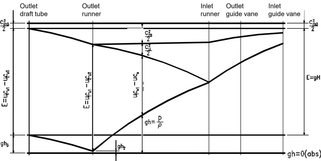
In the Francis turbine, the water flows from the spiral casing to the inlet of the stay vanes, then to the outlet of the stay vanes, and reaches the inlet of the guide vane. The movement of water from the inlet of the guide vane to the outlet of the draft tube can be seen in the top horizontal row of the graph.
At the inlet of the guide vane, the water possesses both kinetic energy and pressure energy. The graph includes a reference line representing atmospheric pressure and another line denoting the net energy (E=gH), which is the total energy or specific energy required to produce unit power from the unit head.
In order to achieve the net specific energy (E=gH), there are losses indicated by the ((Cm3)^2)/2 in the graph. These losses occur in components such as the spiral casing, stay vanes, and runner. The net achievable energy is shown between the lower line and the reference line after deducting losses. The losses are depicted by the gap between the upper and lower lines. To achieve the net specific energy, the input energy carried by the water must be greater, as represented by the upper line and the vapor pressure line.
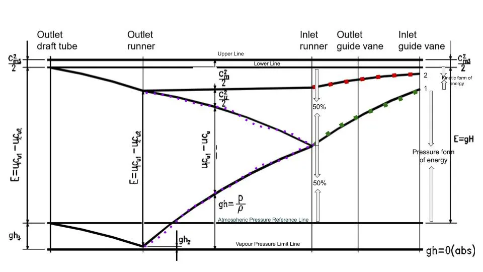
Since the Francis turbine is a mixed-flow turbine, the water possesses both pressure energy and kinetic energy. At the inlet of the guide vane, around 90–95% of the total energy belongs to the pressure form, with the remaining energy in the kinetic form. The line between point 1 and the reference line represents the pressure form of energy, while the line between the lower line and point 1 represents the kinetic form of energy.
As the water glides from the inlet guide vane to the outlet guide vane, the pressure form of energy decreases. Similarly, at the inlet of the runner, the pressure form of energy decreases further while the kinetic form of energy increases. The increasing form of KE can be seen by the gap between the lower line and the green line. This conversion occurs as the water glides, transforming pressure energy into kinetic energy. Comparing the velocities of the inlet and outlet guide vanes reveals the difference in velocity. Additionally, the pressure drop between the inlet and outlet of the guide vane can be observed.
If we refer to the velocity triangle, the absolute velocity (V) of the water has two components: the flow component and the whirl component. The gap between points 1 and 2 resembles the whirl component, while the gap between the upper line and point 2 represents the flow component. The red line helps to separate the flow component and the whirl component. The gap between the upper line and point 1 indicates the velocity component as a whole.
The whirl component acts along the direction of motion of the whirl, while the flow component is perpendicular to the motion of the whirl. At the inlet of the guide vane, the whirl component is higher compared to the flow component. As the water glides from the inlet of the guide vane to the inlet of the runner, both the flow and whirl components increase. The graph shows the increasing total velocity component as water moves from the guide vane to the runner. This increase occurs because the diameter gradually decreases from the inlet of the guide vane to the inlet of the runner, resulting in an increase in flow velocity. The whirl component also increases to match the absolute velocity (U) of the wheel. If the whirl component matches the absolute velocity, the turbine is said to be operating efficiently.
At the inlet of the runner, approximately 50% of the energy appears as pressure energy and the remaining 50% appears as kinetic energy. The kinetic energy is further divided into whirl and flow components, with a reaction ratio of 0.5.
Reaction ratio = pressure form of energy/total energy = 0.5/1 = 0.5
The energy available at the inlet of the runner is a combination of pressure and kinetic energy. As the water glides from the inlet of the runner to the outlet, energy conversion takes place. The energy possessed by the water at the inlet of the runner is hydraulic energy, and the converted energy from the inlet to the outlet of the runner is useful energy or mechanical energy. The highlighted portion of the graph represents useful energy.
The energy possessed by the water at the inlet is hydraulic energy, and the energy extracted at the outlet of the runner is useful or mechanical energy given by, E = U1Cu1-U2Cu2, which can be obtained from the pressure drop. In the graph, you can see the energy gap represented as U1Cu1-UCu. If only this amount of energy is produced by the turbine, it indicates inefficient operation. so, the total useful energy is obtained by further dropping the pressure below the reference atmospheric line. As you can see, prior to reaching the outlet of the runner, the pressure drops below the atmospheric or reference pressure line. The “limit line” represents the maximum vapor pressure line, indicating the acceptable range of pressure drop.
Observing the graph, you can see that the pressure form of energy is again increasing from the outlet of the runner (an inlet of the draft tube) to the outlet of the draft tube.
Returning to the velocity line at the inlet of the runner, you can observe the whirl and flow components. As the water glides from the inlet to the outlet of the runner, the whirl component decreases, and at the outlet, it becomes zero. This decreasing section is depicted in the graph as the (Cu^2)/2 component between the outlet of the runner and the inlet of the runner. Meanwhile, the flow component appears to be uniform (as indicated by the red line) from the inlet to the outlet of the runner.
Now, let’s address why the whirl component is maximum at the inlet of the runner and zero at the outlet of the runner. The whirl component is represented by Vu2 or Cu2 in the velocity diagram.
According to Euler’s turbine equation:
ηh = (U1Cu1 - U2Cu2) / (gHn)
To achieve maximum efficiency at the outlet, the angle α2 should be 90 degrees. Since, Cu2 = V2 cosα2, the whirl component is zero at the outlet when α2 is 90 degrees.
At the outlet of the runner, you can see that the pressure form of energy drops below the reference atmospheric line but does not cross the vacuum pressure limit line. The pressure drops below atmospheric pressure but remains above the vapor pressure of water. If the pressure drops below the vapor pressure line, cavitation problems will arise for the turbine.
The role of the draft tube is crucial. The water available at the outlet of the runner still contains some kinetic energy. Without the draft tube, the remaining kinetic energy in the water would be wasted. The draft tube is an airtight diverging conduit with a cross-sectional area that increases along its length. Applying the continuity equation at the draft tube, Q=A*V, where the velocity of water is high at the outlet of the runner and Q is constant, the area increases with length, resulting in a decrease in kinetic energy and an increase in pressure. This conversion process transforms kinetic energy into pressure energy. The draft tube creates a suction force at the inlet, pulling water with greater velocity, thus helping retain energy that might otherwise be wasted.
The energy conversion diagram presented represents the best efficiency point since the whirl component at the outlet of the runner is zero.
Also Read:
Graphical Interpretation of Energy Conversion in Pelton Turbine
Francis Turbine and its Major Components
Please note that the following interpretation is based on a student’s understanding, so it is important to validate and cross-check the information provided.
This note is prepared by Sandip Paudel from Kathmandu University based on the lecture of Dr. Hari Prasad Neupane.