
The Francis Turbine is a combination of both an impulse and a reaction turbine. It uses both the reaction and impulse forces of water flowing through its blades to produce electricity more efficiently. It is designed for low-head applications ranging from 30 to 650 meters, unlike the Pelton turbine, which is suitable for higher heads (above 400 meters). The Francis turbine operates with a medium discharge (flow rate) and achieves an efficiency of around 96%. The turbine converts a portion of the pressure acting on it into kinetic energy, while the remainder remains as pressure heads. The pressure difference between the guide vanes and the runner is responsible for the motion of the runner; hence, the Francis turbine is also referred to as a reaction turbine.
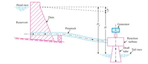
Hydroelectric Power Plant Using a Francis Turbine (Photo Via. R.K. Rajput)
The major components of the Francis Turbine are as follows:
1. Spiral Casing:
The spiral casing resembles a snail’s shell. It is designed to ensure that the water striking the turbine blades flows along a circular axis, allowing for efficient impact. However, as the water moves in a circular pattern, it tends to lose pressure. To maintain consistent pressure, the diameter of the casing gradually reduces, ensuring uniform momentum or velocity of water striking the runner blades. The primary function of the spiral casing is to distribute water evenly to each blade and maintain uniform velocity.
2. Stay Vanes:
Stay vanes, along with guide vanes, guide the water toward the runner blades. Stay vanes remain stationary in their positions and help reduce the swirling motion of water resulting from radial flow as it enters the runner blades. The stay vanes handle the axial load and direct the water from the spiral casing to the guide vanes and runner blades. In vertical Francis’s turbines, where the assembly and other components are vertically aligned above the runner in the shaft, stay vanes are used to minimize the axial load acting on the runner. The stay ring consists of upper and lower ring plates to which stay vanes are welded.
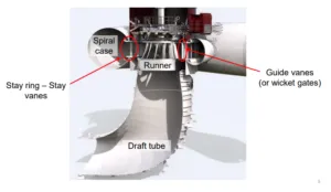
Hydraulic components of Francis Turbine (Photo via. Kathmandu University)
3. Guide Vanes or Wicket Gates:
Guide vanes, also known as wicket gates, are adjustable blades responsible for precisely controlling the water flow as it enters the turbine runner, allowing for optimal performance under various operating conditions.
· Regulating the Water Flow: One of the main functions of guide vanes is to direct the incoming water flow into the turbine runner at the right angle. By adjusting the position of the guide vanes, we can control the flow rate and direction, ensuring efficient energy conversion. This is crucial for achieving the desired operating conditions and maximizing the turbine’s performance.
· Adapting to Different Operating Conditions: The adjustability of guide vanes allows us to adapt the turbine’s operation to different load requirements. Whether we need the turbine to operate at full load, part load, or any other specific condition, we can easily adjust the guide vane angle α1 to match the desired flow rate and optimize the turbine’s performance accordingly.
· Enhancing Energy Conversion: Guide vanes are designed to maximize the conversion of hydraulic energy into mechanical energy. By carefully directing the water flow into the runner, the guide vanes optimize the turbine’s efficiency. They ensure that the water strikes the runner blades at the right angle, utilizing both reaction and impulse forces to extract the maximum energy from the flowing water.
The motion of the guide vanes can be controlled either manually or automatically. In manual operation, we can use a hand wheel to adjust the guide vane angle based on our observations and experience. On the other hand, automatic control systems utilize sensors and feedback mechanisms to continuously monitor and adjust the guide vanes, ensuring precise and efficient turbine operation without constant manual intervention.
4. Runner:
The runner is one of the major components of the Francis turbine and is responsible for converting the driving force of both impulse and reaction effects into rotational motion. It consists of a set of curved blades arranged radially around an axis of rotation. The blades are held in position by a crown plate on the top and a shroud ring at the bottom. The passages formed between the crown, shroud, and adjacent blades carry the flow from the guide vane passages. The runner is designed to generate lift by utilizing thin airfoil-shaped blades, resulting in a pressure side and a suction side. The combination of lift force and impulse force causes the runner to rotate. The pressure side of the runner is where the water strikes.
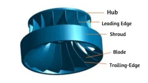
Photo Via. Mandira Adhikari and Laxman Poudel
5. Draft Tube:
The draft tube is an airtight diverging conduit with an increasing cross-sectional area along its length. At the exit of the runner, the pressure is typically lower than atmospheric pressure. Directly discharging the water from the turbine exit to the tailrace is not feasible. Instead, a draft tube is used to gradually increase the area and allow for the discharge of water from the turbine to the tailrace.
The draft tube serves two primary functions:
· Enabling Turbine Elevation: One of the main purposes of the draft tube is to allow the turbine to be installed at a higher elevation than the tailwater level. Additionally, the draft tube aids in the installation and positioning of the turbine. It provides stability and support, allowing the turbine to be securely fixed in various locations, whether underground, on the ground, or above ground. This flexibility in placement makes it easier to integrate the turbine into different hydroelectric power systems.
· Harnessing Kinetic Energy: In reaction turbines, the water flow from the inlet to the exit of the runner does not undergo complete energy conversion. Some portion of the water’s kinetic energy is preserved. To extract this kinetic energy that would otherwise be lost, the draft tube comes into play. By gradually increasing the cross-sectional area along its length, the draft tube allows the conversion of kinetic energy into pressure head as the water approaches the tailrace. This process maximizes the energy efficiency of the turbine and enhances its overall performance. If there had been no draft tube, the kinetic energy of the water would have dissipated, resulting in a significant loss of efficiency. The kinetic head thus saved by the draft tube adds to the effective head of the turbine.
Moreover, the draft tube plays a crucial role in minimizing cavitation. Cavitation is the formation of vapor bubbles in regions of low-pressure flow, which can potentially damage the turbine components. The carefully designed shape and dimensions of the draft tube help control and mitigate cavitation, ensuring the turbine operates smoothly and avoids unnecessary wear and tear.
Also Read:
Graphical Interpretation of Energy Conversion in Pelton Turbine