As we all know, in a Pelton turbine, water is driven through nozzles at great pressure, creating forceful jets of water that impact the turbine’s buckets. The kinetic energy of these jets causes the turbine wheel to spin, which is coupled to a generator, transforming the mechanical energy of the rotating turbine into electrical energy.
In the photo, there is a nozzle located at the top right side, and at the center, we have a graph representing the Energy Conversion in a Pelton Turbine.
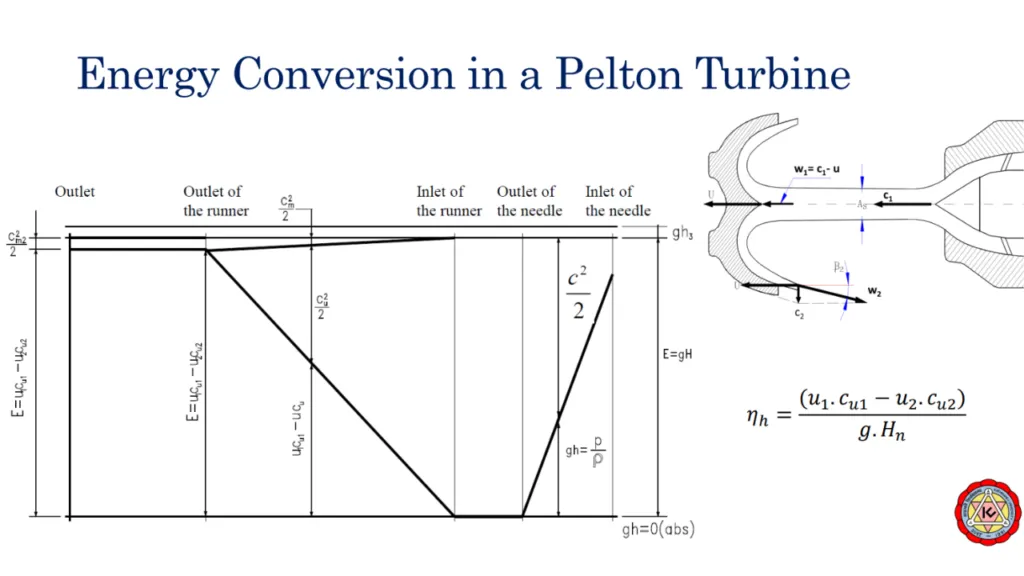
Photo Credit: Kathmandu University.
To begin, let’s understand the process. Water enters through the nozzle and strikes the bucket’s splitter straightly, such that α1=0, dividing the water equally into two cups.
In our case, we are using a medium-speed runner, which means the angle α2 is 90 degrees, resulting in Cu2 being equal to 0. This leads to an efficiency of 100% according to the equation ηh = U1Cu1 / (gHn).
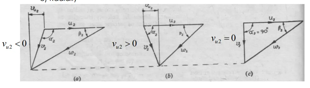
Fig: Velocity triangle of a Pelton Turbine at Outlet
At the inlet of the nozzle, there is a higher chance for maximum potential energy due to the water being under high pressure. As the water flows towards the outlet, all the pressure energy is converted into kinetic energy (KE).
At the nozzle inlet, we have a combination of kinetic energy and potential energy (KE+PE). However, at the outlet, only kinetic energy is present.
The energy represented by gh3 above the tailrace is not utilized for energy conversion. The net head, denoted by H, provides the specific energy (gH), which remains constant.
Hence, at the nozzle inlet, the potential energy is maximum (gh = p/ρ), while the minimum kinetic energy is represented by (c^2)/2.
As the water flows from the nozzle inlet to the outlet, the kinetic energy increases while the potential energy decreases. At the nozzle outlet, only kinetic energy remains, and the potential energy drops to zero.
Throughout the path from the runner inlet to the runner outlet, only kinetic energy (c^2)/2 is present.
At the runner inlet, the velocity component (C1) is equal to the velocity at the cup (Cu). This occurs when the water jet just strikes the runner.
The equation U1Cu1 = U2Cu2 holds true at the runner inlet, implying that no energy conversion takes place at this point.
Energy conversion begins slightly inside the runner, denoted by the point Cu, where the energy converted is U1Cu1 - U2Cu2.
As the water jet enters the runner at different points (as shown in the figure), the hydraulic energy in the form of kinetic energy (KE) decreases, while mechanical energy is generated.

At the runner outlet, the mechanical energy can be calculated as E = U1Cu1 - U2Cu2.
If Cu2 is equal to 0, the efficiency is 100%.
In the graph, we observe a small energy component represented by (Cm2^2)/2, which corresponds to the radial or axial flow. This energy is necessary for the water to flow through the turbine.
Therefore, a complete energy conversion of 100% is not achieved. Some energy is still required for the water to flow up to the tailrace.
Also Read:
Energy Conversion in a Francis Turbine
Please note that the following interpretation is based on a student’s understanding, so it is important to validate and cross-check the information provided.
This note is prepared by Sandip Paudel from Kathmandu University based on the lecture of Dr. Hari Prasad Neupane & Dr. Biraj Singh Thapa.